DESIGNER'S SUMMARY
Fri, 4 Jul 08 11:13
We have learnt a great deal from sailing Vestas SailRocket in the first half of 2008, and can look forward to moving into the ‘record zone’ in the autumn. See also designer's video blog.
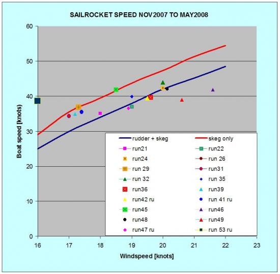
Speed on Target
We are pleased to see that the speeds for nearly every run are in line with predictions and hence confirm the likelihood of getting to 50knots.The last run (53) is well above prediction and represents our highest boat/wind ratio ever!
Plenty to come
Here is a list of the estimated extra speed increases relative to run 32 (44knots peak)
- Strut fairing 1.0k
- String reduction 0.5k
- Rudder retraction 4.0k
- Flap deployment 2.0k
- Met mast 0.2k
- Wing end caps 0.2k
- TOTAL 7.9k
- PLUS 3K PER 1K WIND INCREASE
Steering
We have learnt that the steering behaviour can be quite complex and the process of tuning or ‘balancing’ the boat is more difficult than expected. The result is that Paul's task as pilot has been too demanding and he has not yet felt the required repeatability of response needed to operate the boat in the higher wind speeds especially close to the beach. It is not a forgiving situation sailing 10m from a beach at 45knots and beyond!
Valuable experience has however been acquired with retracting the low speed rudder and operating the hand steered skeg trim tab. We now suspect there are some strong interactions between the two rudders and try to retract the low speed rudder as early as possible.
Naively I thought measurement of the steering trim tab angle would give us a good measure of the steering load and thus enable the correct adjustments of wing position and skeg set angle. In reality its not nearly good enough because:
- The measurement itself is affected by twist/play
- The deployment angles are very small
- You need to estimate the local flow angle which is affected by the main foil upstream. There are significant uncertainties in this.
This was brought home by the large discrepancy (about 100kg for run 48) between our rudder load implied by measurements and those forecast by our mathematical model (we call it the ‘sim’). The sim says there should be about 10kg of load to leeward.
The answer lies in simply measuring the skeg force. We are currently sourcing two types of sensor that can do this and we expect these to be ready for resuming trials in August.
Crash
Unlike all previous crashes the last one was a direct result of a structural failure leading to loss of the skeg.
Without this control surface Vestas SailRocket behaved exactly as she did on previous crashes when there was no fixed skeg. That is – rounding into wind very quickly and backwinding the wing at speed, which caused failure of the crossbeam under compression loads transferred by the strut.
We have strengthened these details and made the skeg structurally independent of the rudder. In addition we have load tested the skeg to 185kg which is well above the load it will bear at top speed.
Wing
While the efficiency and power of the 16m2 wing is not in doubt there are some aspects to handling that are more difficult than we would wish.
The inability to dump most of power on sheet release alone is the key one.
We have a depower trip system which activates the centre flap to a large negative angle. The trouble is its one more thing for Paul to remember and do, and it interacts with the sheeting lines.
Instead we are making modifications to the wing flap fixed settings to achieve the best feathering we can and this will eliminate the backwinding tendency at slight cost in efficiency.
We are seriously considering a MK II wing as it will be possible to get very much better handling with a fresh start. This could be ready in October if we decide to go for it.
These changes to the wing can ease the start up and stopping sequences and give us more time at speed on each run which can be a real advantage especially if we are using the TRIMBLE gps for ratified record attempts when it is allowed to take any 500m course from the full track. As importantly, they also reduce the risk of accidents, particularly if we have to go out in stronger winds above 22knots.
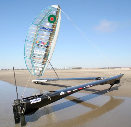
Ground effect
A small but excellent development is the end plate on the cross beam ground effect flap. This not only works by inhibiting the pressure loss near the tip but has stiffened the flap which was bending out of the way of the wind and thus increases lift and efficiency in two ways. It can just be seen in the photo below.